
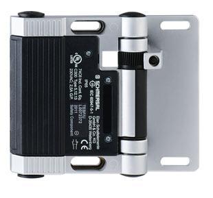
101182714 | TESFA/S/CC/U
Описание
Информация для заказа
![]()
Ordering details | |
|---|---|
| Product type description | TESFA/S/CC/U |
| Article number | 101182714 |
| EAN Code | |
| eCl@ss | 27-27-26-01 |
Approval | |
| Approval |    |
Classification | |
| Standards | EN ISO 13849-1 |
| B10d Normally-closed contact (NC) | 2.000.000 |
| B10d Normally open contact (NO) | 1.000.000 |
| Mission time | 20 Years |
| notice |  |
Global Properties | |
| Permanent light | TESF |
| Standards | EN 60947-5-1 / BG-GS-ET-15 |
Compliance with the Directives (Y/N)  | Yes |
| Materials | |
| - Material of the housings | zinc die-cast |
| - Material of the contacts | Silver-nickel alloy 10 |
| Enclosure color | Black  |
| Weight | 616 |
Mechanical data | |
| Design of electrical connection | Spring pulley connection |
| Cable section | |
| - Min. Cable section | 0,5 |
| - Max. Cable section | 1 |
| Mechanical life | > 1.000.000 operations |
| Switching frequency | 1200/h |
| notice | All indications about the cable section are including the conductor ferrules. |
| Opening angle | 180° |
| Positive break angle | 10° |
| additional hinge (Y/N) | No |
| Adjustable switching angle (Y/N) | Yes |
| Alignment aid (Y/N) | Yes |
| Mounting inside (Y/N) | No |
| Mounting outside (Y/N) | No |
Ambient conditions | |
| Ambient temperature | |
| - Min. environmental temperature | −25 °C |
| - Max. environmental temperature | +65 °C |
| Protection class | IP65 |
Electrical data | |
| Design of control element | Normally open contact (NO), Opener (NC) |
| Switching principle | Creep circuit element |
| Number of auxiliary contacts | 2 |
| Number of safety contacts | 2 |
| Rated impulse withstand voltage Uimp | 2.5 kV |
| Rated insulation voltage Ui | 250 V |
| Thermal test current Ithe | 2.5 A |
| Utilisation category | AC-15: 230 V / 2 A, DC-13: 24 V / 1 A |
| Max. fuse rating | 2 A gG D-fuse |
| Switching of low voltages | 1 / 5 |
ATEX | |
| Explosion protection categories for gases | None |
| Explosion protected category for dusts | None |
Dimensions | |
 Ordering details
- Цена: Цену уточняйте
Информация для покупателя
ООО «ФилФар Технолоджи»
220036, г. Минск, ул. Западная, д.13, к.519
Дата регистрации в Торговом реестре/Реестре бытовых услуг: 18.03.2015
Номер в Торговом реестре/Реестре бытовых услуг: 220993, Республика Беларусь
УНП: 192123248
Регистрационный орган: Минский горисполком
Дата регистрации компании: 18.09.2013
Ссылка на свидетельство/лицензию
Режим работы:
| День | Время работы |
|---|---|
| Понедельник | 09:00-17:00 |
| Вторник | 09:00-17:00 |
| Среда | 09:00-17:00 |
| Четверг | 09:00-17:00 |
| Пятница | 09:00-17:00 |
| Суббота | Выходной |
| Воскресенье | Выходной |