
101147091 | BN 325-R-1279
Описание
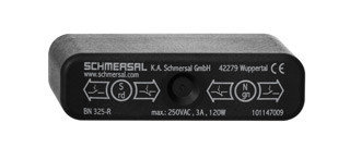
Информация для заказа
![]()
Ordering details | |
|---|---|
| Product type description | BN 325-R-1279 |
| Article number | 101147091 |
| EAN Code | 4030661141299 |
| eCl@ss | 27-27-01-04 |
Approval | |
| Approval | - |
Global Properties | |
| Permanent light | BN 325 |
| Standards | - |
Compliance with the Directives (Y/N)  | Yes |
| suitable for elevators (Y/N) | Yes |
| Mounting | rear with 2 Threaded bolt |
| Active principle | Magnetic drive |
| Materials | |
| - Material of the housings | Plastic, glass-fibre reinforced thermoplastic |
| Housing construction form | rectangular, flat |
| Weight | 98 |
| Recommended actuator | BP 10 N, BP 10 S, 2 x BP 10 N, 2 x BP 10 S, BP 15 N, BP 15 S, 2 x BP 15/2 N, 2 x BP 15/2 S, BP 34 N, BP 34 S, BP 20 N, BP 20 S, BP 31 N, BP 31 S, BP 11 N, BP 11 S, 2 x BP 11 N, 2 x BP 11 S, BP 12 N, BP 12 S, 2 x BP 12 N, 2 x BP 12 S, BP 21 N, BP 21 S, 2 x BP 21 N, 2 x BP 21 S, BE 20, BE 20 N(S) ST 24VDC, BE 20 N(S) 48VDC |
| - Lift switchgear | BP 10, 2 x BP 10, 2 x BP 15/2, BP 15, BP 34 |
Mechanical data | |
| Design of electrical connection | Cable output left and 2 shielding plates |
| Cable length | 1 |
| Mechanical life | 1.000.000.000 operations |
| Electrical lifetime | 1.000.000 … 1.000.000.000 operations |
| Actuating planes | front side |
| Switch distance | 5 … 55 BP 10N = 10 mm BP 10S = 10 mm 2 x BP 10N = 15 mm 2 x BP 10S = 15 mm BP 15N = 12 mm BP 15S = 12 mm 2 x BP 15/2N = 17 mm 2 x BP 15/2S = 17mm BP 34N = 10 ... 25mm BP 34S = 10 ... 25 mm BP 20N = 5 ... 20 mm BP 20S = 5 ... 20 mm BP 31N = 5 ... 20 mm BP 31S = 5 ... 20 mm BP 11N = 10 mm BP 11S = 10 mm 2 x BP 11N = 20 mm 2 x BP 11S = 20 mm BP 12N = 15 mm BP 12S = 15 mm 2 x BP 12N = 10 ... 25 mm 2 x BP 12S = 10 ... 25 mm BP 21N = 15 ... 40 mm BP 21S = 15 ... 40 mm 2 x BP 21N = 20 ... 55 mm 2 x BP 21S = 20 ... 55 mm BE 20 = 20 mm BE 20N = 15 mm BE 20S = 15 mm |
| - notice | Actuating distance up to 55 mm depending on actuating magnet and version The specifications with regard to the switching distances apply to the actuation of the individually mounted devices without ferromagnetic influence. Any change of the distance, positive either negative, is possible due to ferromagnetic interference. When multiple actuating magnets are used, the mutual interference must be observed. |
| Type of actuation | Magnet |
| restistance to shock | 50 / 11 |
| Resistance to vibration | 10 … 55 HZ, Amplitude 1 mm |
| Bounce duration | 0,3 … 0,6 |
| Latching (Y/N) | Yes |
| Actuating speed | 18 |
| Switching point accuracy | ± 0,25 mm |
Ambient conditions | |
| Ambient temperature | |
| - Min. environmental temperature | −25 |
| - Max. environmental temperature | +70 |
| Protection class | IP67 |
Electrical data | |
| Design of control element | bistable contact |
| Number of snap-in contacts | 1 |
| Switching time - Close | 1.5 |
| Switching time - Open | 0,5 |
| Switch frequency | <> |
| Dielectric strength | > 600 (50 ) |
| Switching voltage | 250 |
| Switching current | 3 A |
| Switching capacity | 120 |
 Ordering details
- Цена: Цену уточняйте
Информация для покупателя
ООО «ФилФар Технолоджи»
220036, г. Минск, ул. Западная, д.13, к.519
Дата регистрации в Торговом реестре/Реестре бытовых услуг: 18.03.2015
Номер в Торговом реестре/Реестре бытовых услуг: 220993, Республика Беларусь
УНП: 192123248
Регистрационный орган: Минский горисполком
Дата регистрации компании: 18.09.2013
Ссылка на свидетельство/лицензию
Режим работы:
| День | Время работы |
|---|---|
| Понедельник | 09:00-17:00 |
| Вторник | 09:00-17:00 |
| Среда | 09:00-17:00 |
| Четверг | 09:00-17:00 |
| Пятница | 09:00-17:00 |
| Суббота | Выходной |
| Воскресенье | Выходной |