Ordering details | |
---|---|
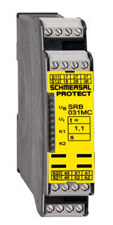
Product type description | SRB031MC-24V/1,1SEC |
Article number | 101190685 |
EAN Code | 4250116202256 |
eCl@ss | 27-37-19-01 |
Approval | |
Approval | ![]() ![]() |
Classification | |
Standards | EN ISO 13849-1, IEC 61508, EN 60947-5-1 |
PL | bis d (STOP 1) |
Control category | bis 3 (STOP 1) |
DC | > 60% (STOP 1) |
CCF | > 65 points |
PFH value | 2 x 10⁻⁷/h (STOP 1) |
SIL | bis 3 (STOP 0) |
Mission time | 20 Years |
- notice | The PFH value is applicable for the combinations listed in the table for contact load (K) (current through enabling paths) and switching cycle number (n-op/y). In case of 365 operating days per year and a 24-hour operation, this results in the specified switching cycle times (t-cycle) for the relay contacts. Diverging applications on request. ![]() |
Global Properties | |
Permanent light | SRB031MC |
Standards | IEC/EN 60204-1, EN 60947-5-1, EN ISO 13849-1, IEC 61508 |
Compliance with the Directives (Y/N) ![]() | Yes |
Climatic stress | EN 60068-2-78 |
Mounting | snaps onto standard DIN rail to EN 60715 |
Terminal designations | IEC/EN 60947-1 |
Materials | |
- Material of the housings | Plastic, glass-fibre reinforced thermoplastic, ventilated |
- Material of the contacts | AgSn0, Ag-Ni, self-cleaning, positive action |
Weight | 250 |
Start conditions | Automatic or Start button |
Start input (Y/N) | Yes |
Feedback circuit (Y/N) | Yes |
Start-up test (Y/N) | No |
Reset after disconnection of supply voltage (Y/N) | No |
Automatic reset function (Y/N) | Yes |
Reset with edge detection (Y/N) | No |
delay time | 1.1 s |
Pull-in delay | |
- ON delay with automatic start | typ. 100 ms |
Drop-out delay | |
- Drop-out delay in case of power failure | delay time ± 30% for 24 VDC and Duty cycle > 3.5 s |
- Drop-out delay in case of emergency stop | delay time ± 30% for 24 VDC and Duty cycle > 3.5 s |
Mechanical data | |
Connection type | Screw connection |
Cable section | |
- Min. Cable section | 0,25 |
- Max. Cable section | 2.5 |
Pre-wired cable | rigid or flexible |
Tightening torque for the terminals | 0,6 |
Detachable terminals (Y/N) | No |
Mechanical life | 10.000.000 operations |
Electrical lifetime | Derating curve available on request |
restistance to shock | 30 g / 11 ms |
Resistance to vibration To EN 60068-2-6 | 10…55 HZ, Amplitude 0,35 mm |
Ambient conditions | |
Ambient temperature | |
- Min. environmental temperature | −25 °C |
- Max. environmental temperature | +60 °C |
Storage and transport temperature | |
- Min. Storage and transport temperature | −40 °C |
- Max. Storage and transport temperature | +85 °C |
Protection class | |
- Protection class-Enclosure | IP40 |
- Protection class-Terminals | IP20 |
- Protection class-Clearance | IP54 |
Air clearances and creepage distances To IEC/EN 60664-1 | 4 kV / 2 |
- Rated impulse withstand voltage Uimp | 4 kV |
- Overvoltage category | III To IEC/EN 60664-1 |
- Degree of pollution | 2 To IEC/EN 60664-1 |
Electromagnetic compatibility (EMC) | |
EMC rating | conforming to EMC Directive |
Electrical data | |
Rated DC voltage for controls | |
- Max. rated DC voltage for controls | 20.4 V |
- Max. rated DC voltage for controls | 28.8 V |
Rated AC voltage for controls, 50 Hz | |
- Min. rated AC voltage for controls, 50 Hz | 20.4 V |
- Max. rated AC voltage for controls, 50 Hz | 26.4 V |
Rated AC voltage for controls, 60 Hz | |
- Min. rated AC voltage for controls, 60 Hz | 20.4 V |
- Max. rated AC voltage for controls, 60 Hz | 26.4 V |
Contact resistance | max. 100 mΩ |
Power consumption | max. 2 W; 4.9 VA |
Type of actuation | AC/DC |
Rated operating voltage Ue | 24 VDC−15% / +20% residual ripple max. 10% 24 VAC−15% / +10% |
Frequency range | 50 / 60 HZ |
Electronic protection (Y/N) | Yes |
Fuse rating for the operating voltage | Internal electronic trip, tripping current > 0,5 A, Reset after approximately 1 second/s |
- S11, S12, S21, S22 | 24 VDC, Test current: 10 mA |
Bridging in case of voltage drops | approx. Time delay ± 30% for 24 VDC and Duty cycle > 3.5 s |
Inputs | |
Monitored inputs | |
- Short-circuit recognition (Y/N) | optional |
- Wire breakage detection (Y/N) | Yes |
- Earth connection detection (Y/N) | Yes |
Number of shutters | 0 piece |
Number of openers | 2 piece |
Cable length | 1-channel without cross-wire detection: 1500 m with 1.5 mm²; 2500 m with 2.5 mm² 2-channel with/ without cross-wire detection |
Conduction resistance | max. 40 Ω |
Outputs | |
Stop category | 0 / 1 |
Number of safety contacts | 3 piece |
Number of signalling outputs | 1 piece |
Switching capacity | |
- Switching capacity of the safety contacts | max. 230 VAC, 8 A ohmic ( inductive in case of appropriate protective wiring) |
- Switching capacity of the auxiliary contacts | 24 VDC, 2 A |
Fuse rating | |
- Protection of the safety contacts | 8 A slow blow |
- Fuse rating for the auxiliary contacts | 2 A slow blow |
Utilisation category To EN 60947-5-1 | AC-15: 230 V / 6 A DC-13: 24 V / 6 A |
Number of undelayed semi-conductor outputs with signaling function | 0 piece |
Number of undelayed outputs with signaling function (with contact) | 0 piece |
Number of delayed semi-conductor outputs with signaling function. | 0 piece |
Number of delayed outputs with signalling function (with contact). | 1 piece |
Number of secure undelayed semi-conductor outputs with signaling function | 0 piece |
Number of secure, undelayed outputs with signaling function, with contact. | 0 piece |
Number of secure, delayed semi-conductor outputs with signaling function | 0 piece |
Number of secure, delayed outputs with signaling function (with contact). | 3 piece |
LED switching conditions display | |
LED switching conditions display (Y/N) | Yes |
Number of LED´s | 4 piece |
LED switching conditions display | |
- The integrated LEDs indicate the following operating states. | |
- Position relay K1 | |
- Position relay K2 | |
- Supply voltage UB | |
- Internal operating voltage Ui | |
Miscellaneous data | |
Applications | ![]() ![]() ![]() ![]() ![]() |
Dimensions | |
Dimensions | |
- Width | 22.5 mm |
- Height | 100 mm |
- Depth | 121 mm |
notice | |
Inductive loads (e.g. contactors, relays, etc.) are to be suppressed by means of a suitable circuit. | |
notice - Wiring example | |
To secure a guard door up to PL 4 and Category #03# | |
Monitoring 1 guard door(s), each with a magnetic safety sensor of the BNS range | |
The feedback circuit monitors the position of the contactors Ka and Kb. | |
If only one external relay or contactor is used to switch the load, the system can be classified in Control Category 3 to EN 954-1, if exclusion of the fault “Failure of the external contactor” can be substantiated and is documented, e.g. by using a reliable down-rated contactor. A second contactor leads to an increase in the level of security by redundant switching to switch the load off. | |
Automatic start: The automatic start is programmed by connecting the feedback circuit to the terminals X1/X2. If the feedback circuit is not required, establish a bridge | |
The wiring diagram is shown with guard doors closed and in de-energised condition. |
По вопросу интересующей Вас продукции, пожалуйста, свяжитесь с нами:
8 (029) 555-8-000 | |
8 (044) 555-8-000 | |
8 (017) 255-8-000 |
Или отправьте нам запрос на e-mail: zapros@filfar.by