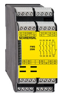
Ordering details | |
---|---|
Product type description | FWS 2506C |
Article number | 101181694 |
EAN Code | 4030661323251 |
eCl@ss | 27-37-19-01 |
Approval | |
Approval | ![]() ![]() ![]() |
Classification | |
Standards | EN ISO 13849-1, IEC 61508 |
PL | up d |
Control category | up 3 |
PFH value | 1.0 x 10⁻⁷/h |
SIL | up 2 |
Mission time | 20 Years |
Global Properties | |
Permanent light | FWS 2506 |
Standards | IEC/EN 60204-1, EN ISO 13849-1, BG-GS-ET-20 |
Compliance with the Directives (Y/N) ![]() | Yes |
Climatic stress | EN 60068-2-3, BG-GS-ET-14 |
Mounting | snaps onto standard DIN rail to EN 60715 |
Terminal designations | IEC/EN 60947-1 |
Materials | |
- Material of the housings | Plastic, glass-fibre reinforced thermoplastic, ventilated |
- Material of the contacts | Ag-Ni, 0,2 µm gold flashed |
Weight | 320 |
Start input (Y/N) | No |
Feedback circuit (Y/N) | Yes |
Reset after disconnection of supply voltage (Y/N) | No |
Automatic reset function (Y/N) | No |
Reset with edge detection (Y/N) | Yes |
Mechanical data | |
Connection type | Screw connection |
Cable section | |
- Min. Cable section | 0,2 |
- Max. Cable section | 2.5 |
Pre-wired cable | rigid or flexible |
Tightening torque for the terminals | 0,6 |
Detachable terminals (Y/N) | No |
Mechanical life | 20.000.000 operations |
Electrical lifetime | 150.000 operations for 230 VAC, 5 A (cos φ = 1) |
hysteresis | 10 % of standstill frequency |
restistance to shock | 30 g / 11 ms |
Resistance to vibration To EN 60068-2-6 | 10…55 HZ, Amplitude 0,35 mm |
Standstill frequency | Inputs X2 / X4: 1 / 1 |
Ambient conditions | |
Ambient temperature | |
- Min. environmental temperature | 0 |
- Max. environmental temperature | +55 |
Storage and transport temperature | |
- Min. Storage and transport temperature | −25 |
- Max. Storage and transport temperature | +70 |
Protection class | |
- Protection class-Enclosure | IP40 |
- Protection class-Terminals | IP20 |
- Protection class-Clearance | IP54 |
Air clearances and creepage distances To IEC/EN 60664-1 | |
- Rated impulse withstand voltage Uimp | 4.8 kV |
- Overvoltage category | III To VDE 0110 |
- Degree of pollution | 2 To VDE 0110 |
Electromagnetic compatibility (EMC) | |
EMC rating | 10 V/m |
Electrical data | |
Rated DC voltage for controls | |
- Max. rated DC voltage for controls | 20.4 |
- Max. rated DC voltage for controls | 253 |
Rated AC voltage for controls, 50 Hz | |
- Min. rated AC voltage for controls, 50 Hz | 20.4 |
- Max. rated AC voltage for controls, 50 Hz | 253 |
Rated AC voltage for controls, 60 Hz | |
- Min. rated AC voltage for controls, 60 Hz | 20.4 |
- Max. rated AC voltage for controls, 60 Hz | 253 |
Contact resistance | max. 100 mΩ |
Power consumption | <> |
Type of actuation | AC/DC |
Rated operating voltage Ue | 24 … 230 VAC/DC |
Operating current Ie | 0,4 A |
Electronic protection (Y/N) | No |
Inputs | |
Monitored inputs | |
- Short-circuit recognition (Y/N) | No |
- Wire breakage detection (Y/N) | Yes |
- Earth connection detection (Y/N) | No |
Input frequency | 1000 |
min. pulse duration | 500 |
Input resistance | approx. 4000 Ω at GND |
Input signal "1" | 10 … 30 VDC |
Input signal "0" | 0 … 2 VDC |
Cable length | 100 m with 0,75 mm² (for Rated voltage) |
Outputs | |
Stop category | 0 |
Number of safety contacts | 4 |
Number of auxiliary contacts | 1 |
Number of signalling outputs | 2 |
Switching capacity | |
- Switching capacity of the safety contacts | min. 10 mA, max. 6 A |
- Switching capacity of the signaling/diagnostic outputs | Y1, Y2: max. 100 mA |
Fuse rating | |
- Protection of the safety contacts | 6 A gG D-fuse |
- Fuse rating for the signaling/diagnostic outputs | short-circuit proof |
Signalling output | Y1: Authorized operation, safety contacts on; Y2: Error, high signal |
Utilisation category To EN 60947-5-1 | AC-15: 230 V / 3 A DC-13: 24 V / 2 A |
Number of undelayed semi-conductor outputs with signaling function | 2 |
Number of undelayed outputs with signaling function (with contact) | 0 |
Number of delayed semi-conductor outputs with signaling function. | 0 |
Number of delayed outputs with signalling function (with contact). | 0 |
Number of secure undelayed semi-conductor outputs with signaling function | 0 |
Number of secure, undelayed outputs with signaling function, with contact. | 0 |
Number of secure, delayed semi-conductor outputs with signaling function | 0 |
Number of secure, delayed outputs with signaling function (with contact). | 0 |
LED switching conditions display | |
LED switching conditions display (Y/N) | Yes |
Number of LED´s | 1 |
Integral system diagnosis $missingShortName$ | |
Integral system diagnosis ISD | |
- The following faults are registered by the safety monitoring modules and indicated by ISD | |
- Interruption of the connections to the inductive proximity switches | |
- Failure of the safety relay to pull-in or drop-out | |
- Fault on the input circuits or the relay control circuits of the safety monitoring module | |
- Failure of the proximity switches | |
- Failure of one channel being evaluated | |
Miscellaneous data | |
Applications | ![]() |
Dimensions | |
Dimensions | |
- Width | 45 mm |
- Height | 100 mm |
- Depth | 121 mm |
notice | |
Inductive loads (e.g. contactors, relays, etc.) are to be suppressed by means of a suitable circuit. | |
notice - Wiring example | |
To monitor one guard door at plants with dangerous run-on movements up to PL d and Category 3 | |
Standstill monitoring for unlocking solenoid interlocks | |
The solenoid interlock can be opened, when the fail-safe standstill monitor has detected the end of the run-on movement by means of two inductive proximity switches. When the button (E) is actuated, the coil of the solenoid interlock is energised. | |
If only one inductive proximity switch is connected to the standstill monitor, the standstill frequencies must be identical and inputs X2 and X4 must be bridged. | |
For suitable IFL range p-type inductive proximity switches, refer to "Schmersal Catalogue Automatisierungstechnik". | |
The wiring diagram is shown with guard doors closed and in de-energised condition. | |
The ISD tables (Intergral System Diagnostics) for analysis of the fault indications and their causes are shown in the appendix. |
По вопросу интересующей Вас продукции, пожалуйста, свяжитесь с нами:
8 (029) 555-8-000 | |
8 (044) 555-8-000 | |
8 (017) 255-8-000 |
Или отправьте нам запрос на e-mail: zapros@filfar.by